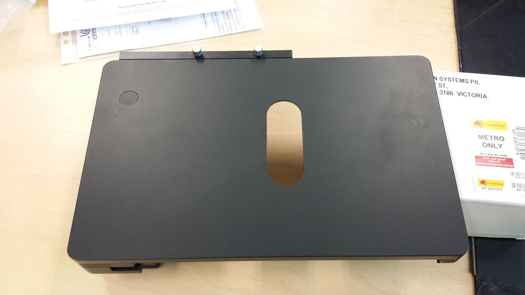
(Optional extra) - Piezo-motor driven stage This stage is supplied with a separate high-voltage power supply / controller. The controller plugs into the microscope’s CAN bus, and the Piezo stage is thus controlled by our software, as is the case for the standard stepper-motor stages. Apart from being suitable for labs with high-volume sample throughput, users tell us that this stage is much smoother and more accurate than the stepper motor stage. The price we will advise is for SUBSTITUTING a Piezo stage for the stepper stage when purchasing one of our 3 standard systems. Each Piezo stage is supplied with patented Autoscan AB and C slide holders. Please note : A different price applies for an outright stage purchase.
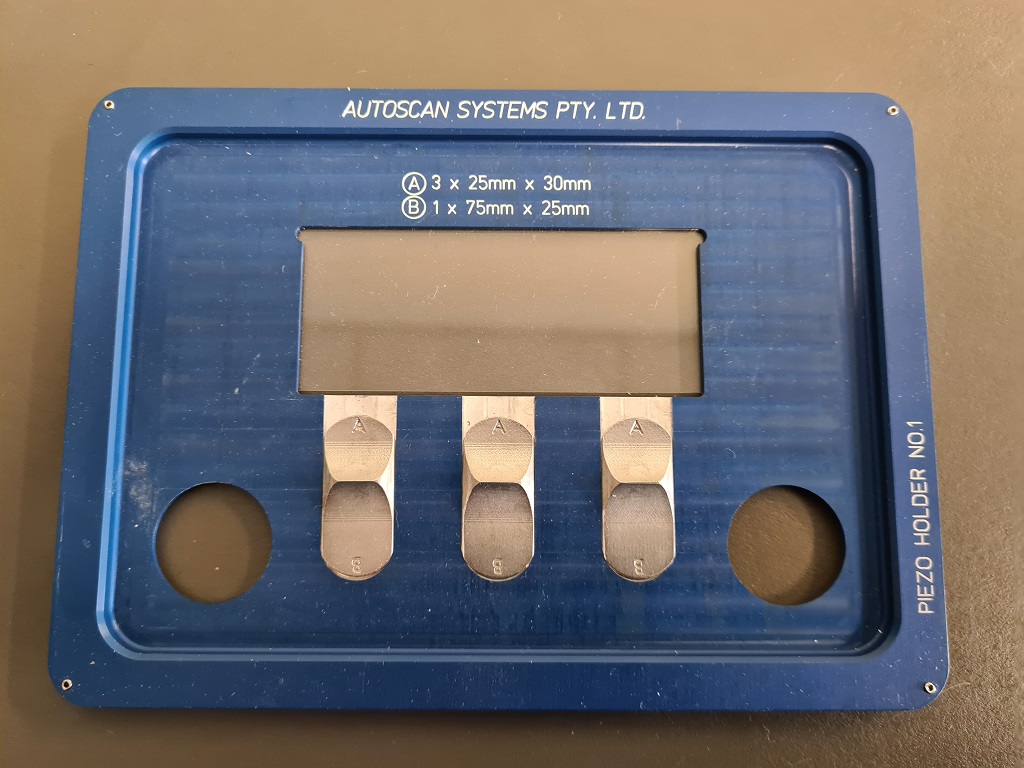
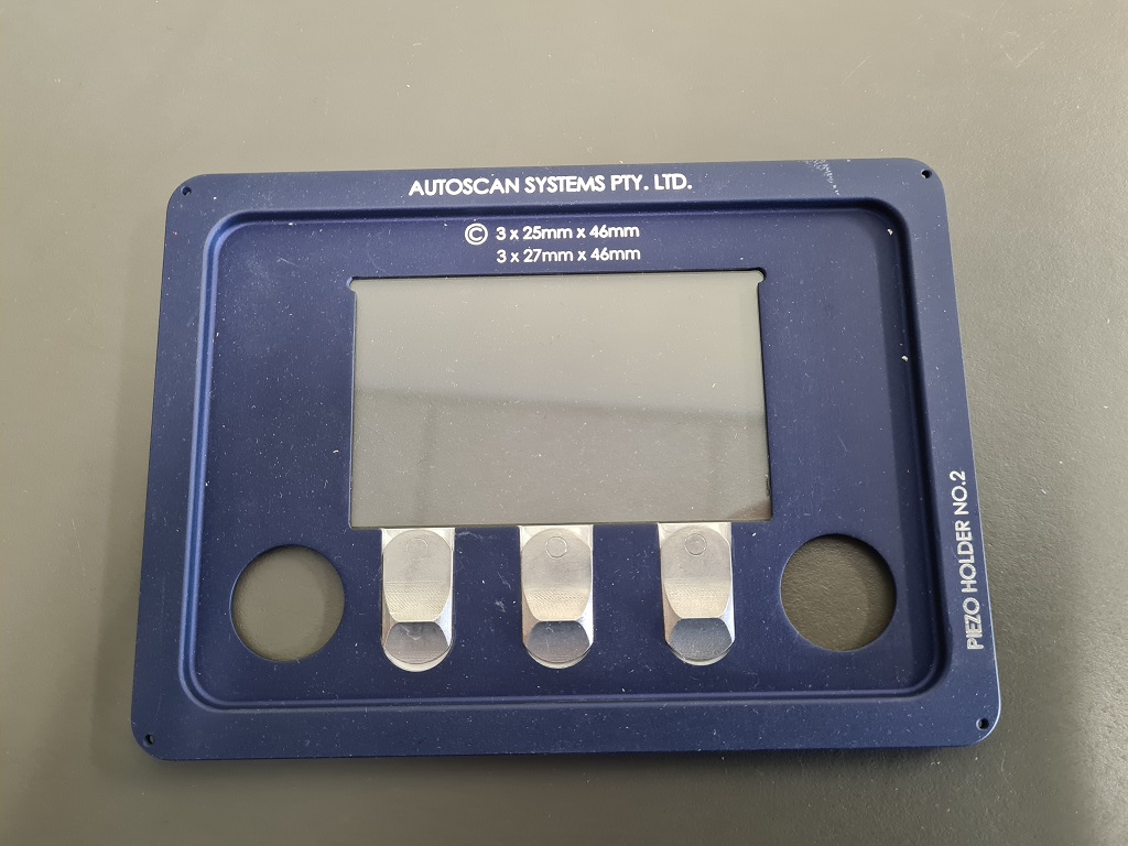
(Standard with optional Piezo-motor driven stage) - Autoscan slide AB and C holders for Piezo-motor stage
These slide holders are supplied with every Piezo-motor driven stage.
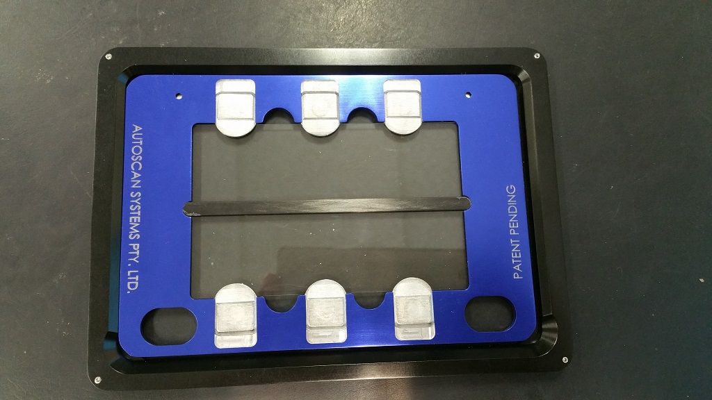
(Optional extra) - Autoscan multi-slide holders for Piezo stage These patented slide holders allow the continuous analysis of up to 6 slides, (at the University of Melbourne format of 25 x 30 mm). (These can be cut from standard slides, but we are also able to supply lots of these slides). Each set consists of two slide holders, with one adapter frame for fast release/replacement. The image shows a slide holder in its adapter frame.
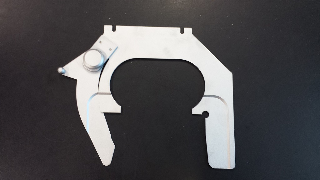
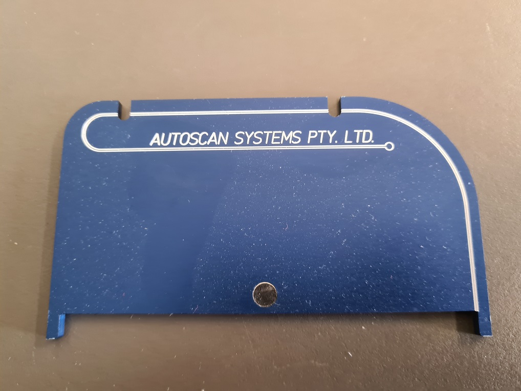
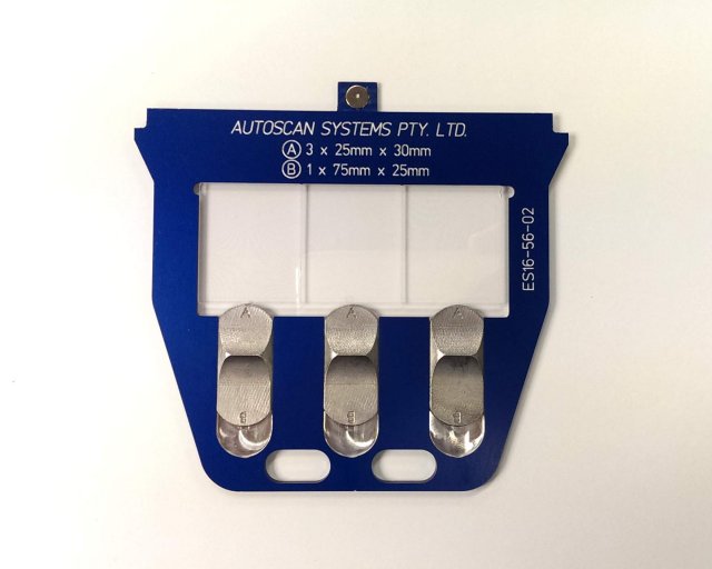
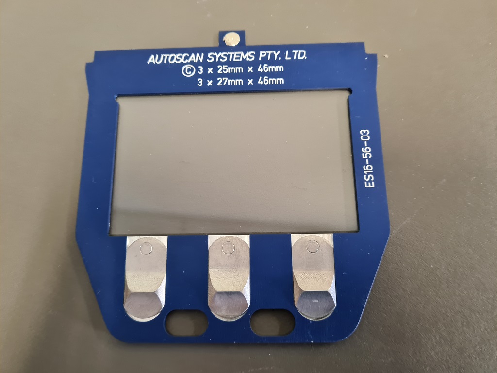
(Standard for the usual stepper motor stages which we supply with all systems) The items supplied with our standard systems are :
(Left image) : A Zeiss slide holder for a single standard 25 x 75 mm glass slide. (Second image from left) : An adapter which mounts in exactly the same place as the standard Zeiss slide holder (using two screws to quickly attach to the stepper-motor stage). This unit adapts the stage to our patented Autoscan AB and C type slide holders, and incorporates a magnet which holds our slide holders securely in place, but allows fast exchange of samples on the bench, rather than on the stage. (Second image from right) : Our AB-type slide holder, which will accept either a single traditional microscope slide (25 x 75 mm), or three of the new 25 x 30 mm sample slides. The buttons are reversible, to ensure secure holding of the sample, even of the slide holder is turned upside-down. (Image on right) : Our C-type slide holder, which will accept either commercially purchased "petrographic" slides (27 x 46 mm), or similar slides cut in the lab from standard 25 x 75 mm slides. We call these "pseudo-petrographic" slides, and they measure 25 x 46 mm in size.
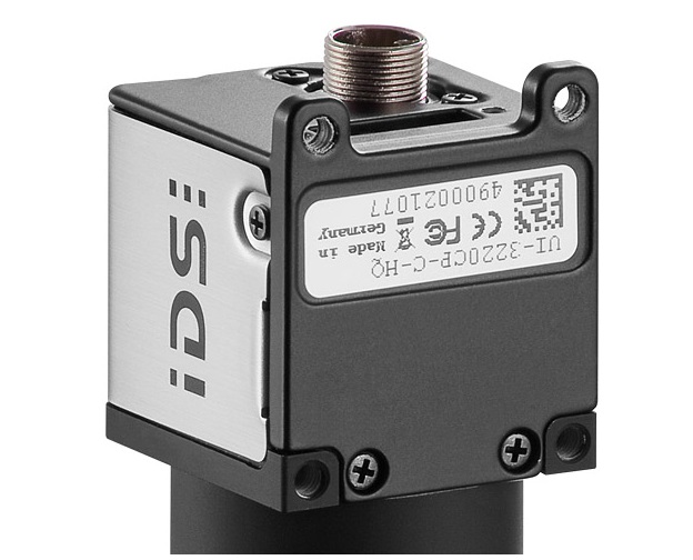
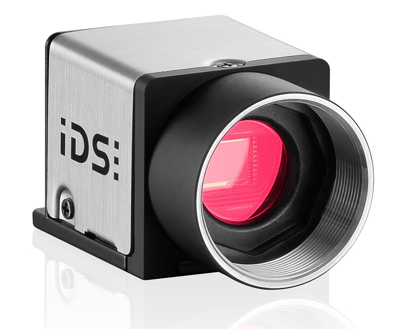
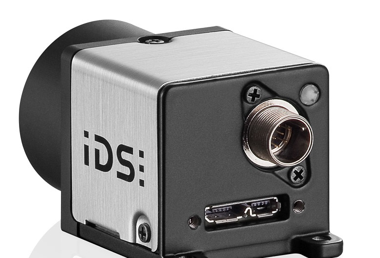
(Standard with all systems) - IDS high resolution and fast frame rate colour digital camera
This 4 MP camera with a 1 inch sensor offers 12-bit resolution at 2048 x 2048 pixels, and with a maximum frame rate of 75 frames/second. Since the most critical part of fission track dating takes place with an objective of 100 x, the resoltuion of the image emerging from the top of the Zeiss AxioImager microscopes is ALWAYS much lower than 4 MP. So using a camera with a higher resolution is pointless.
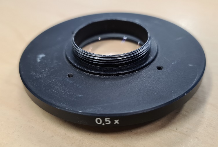
(Standard with all systems) - C-mount (Camera mount) for camera
This items matches the chip size in the camera, thus obtaining an image on the PC monitor which matches the image seen when looking through the microscope. The C-mount for the IDS UI-3370CP-C-HQ camera uses a "0.63x" reduction lens, whereas the IDS U3-3080-CP cameras use a "0.5x" reduction lens, and the Zeiss ICc3 cameras (as well as the AVT Oscar F-320C camera) use a "1.0x" reduction lens. Unless such a lens is used, the monitor image will be larger than the microscope image, and the camera may not fit on to the Zeiss microscope.
The image shows a typical C-mount. (Apart from the reduction lens, the C-mount acts as an adapter to allow the camera to be mounted on top of the microscope. So the bottom is usually a threaded ring which fits on to the microscope, while the top is a standard camera thread, which screws directly into each of the camera types shown above).
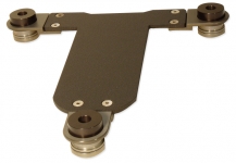
(Standard with Deluxe system. Optional extra for other systems) - Anti-vibration platform These are required in situations of significant vibration. Usually, this will not be the case, but remember that FTD work takes place at 1000x magnifications. This is not only the maximum useful magnification for visible light, but will magnify small vibrations.
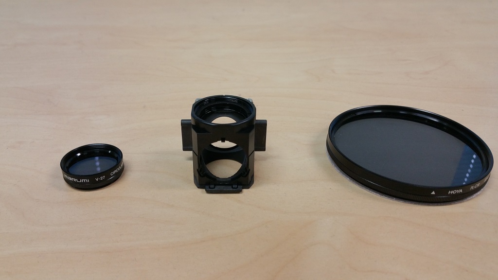
(Standard with Deluxe system. Optional extra for other systems) - CPL Kit This kit consists of a spare mirror cube and two circularly polarized filters. These allow the user to identify suitable apatite grains. The normal process of identifying suitable grains is quite tedious, and involves viewing each grain at high magnification to check whether the etch pits all lie along the C-axis.
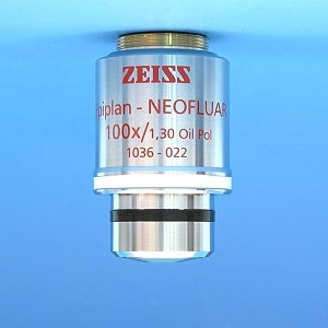
(Optional extra) - 100x Oil-immersion objective 100x/1.3 Oil (WD 0.37 mm) Epiplan-Neofluar objective with 20 ml bottle of Immersol 518 N. This objective is often used by FTD researchers who work with zircons. Other options include an Optovar, a 150x dry objective, or 16x eyepieces. Please contact us for details.
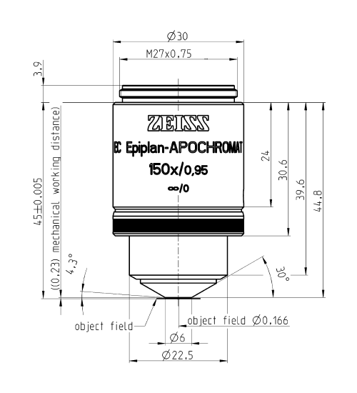
(Optional extra) - 150x dry objective 150x Epiplan-Neofluar objective. This objective is often used by FTD researchers who work with zircons. Other options include an Optovar, a 150x dry objective, or 16x eyepieces. Please contact us for details.
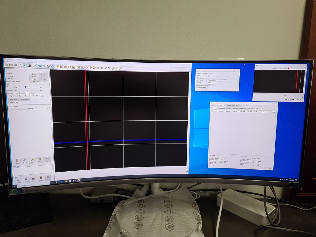
(Optional extra) - 34 Inch curved wide-screen monitor INSTEAD OF 2 x 24 inch monitors: These large monitors are used to obtain simultaneous images of the various TrackWorks windows on the one monitor. They also minimize the desk space required, and are even delivered with a wall-mount plate !
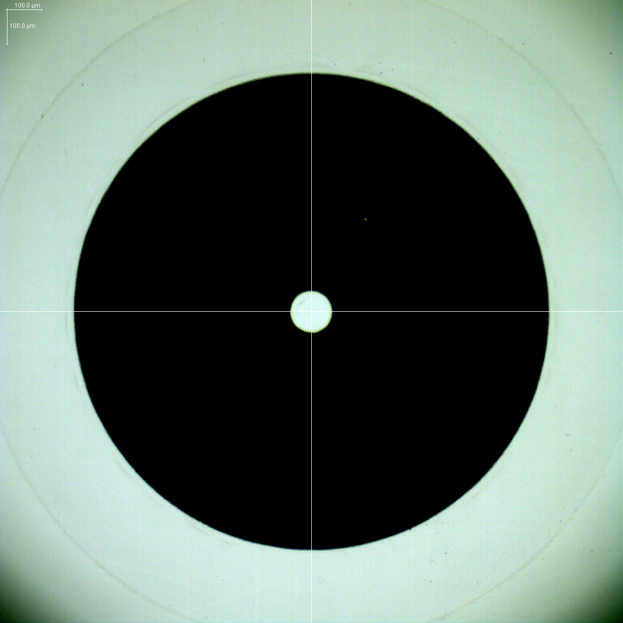
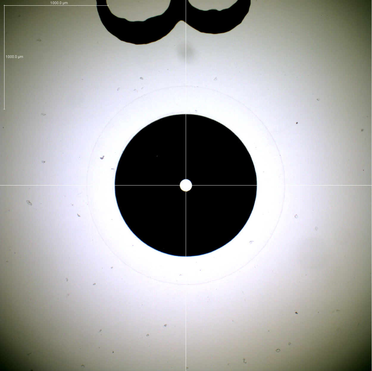
Autoscan slides (25 x 30 mm) with ready-made bevel and numbered coordination marks: These specially prepared slides are available in lots of 1,000, 2,000, 5,000 or 10,000. The big advantage is that they will fit most common laser ablation and ICP-MS devices. The bevels can be applied in most labs, but a common problem is that the lab people "overgrind" the bevels. This results in the slides riding up in their holders, rather than being securely held. We also supply coordination marks, numbered "1" to "3" (same as used by the University of Melbourne). These allow the user (since the holes are in exactly the same location every time) to use the automatic coordination facility in our software. One important advantage with the coordination marks (apart from cost and ease of use) will be that the 2.5x and 5x objectives will no longer be needed for automated coordination mark location. Instead, the usual 10x objective is able to be used, since the diameter of the coordination "doughnut" is less than 1,500 microns (1.5 mm). (Shown in the diagrams above : LEFT IMAGE - 10x objective view, showing coordination mark and centering hole. If you open this image in a new tab, you will see the scale bars at the top left. The scale bars are 100 microns in X and Y. RIGHT IMAGE - 5x objective view of coordination mark 3, showing the coordination mark, the number 3, and the centering hole, which is of the order of 100 microns (as well as a scale bar). The 5x objective is no longer necessary to view the entire coordination mark. Clicking on the centering hole of a coordination mark automatically centres it (and thus the centering hole). The slides are supplied in boxes of 50 at a time.
